Projects
Projects
Mechanical Capstone | Redesign of the CH-47 Chinook Avionics Rack
Project Overview:
My team and I were tasked by Boeing to redesign the avionics rack of the CH-47 Chinook helicopter for the purpose of reducing the weight of the shelves without compromising the overall structural integrity, while considering techniques used to manufacture the shelves to ensure manufacturability.
Project Constraints:
Loading Constraints:
-
MIL-STD-1290A Section 5.5.3.2 Batteries and Electrical Components
-
Defines that shelf must withstand all loading from the avionics placed on the rack in addition to 20G loads in all directions
-
Vibrational Constraints:
-
The below frequencies are to be avoided
Space Constraints:
-
All avionics on the same rack are to be equally spaced for cable routing
-
The avionics on rack #4 all require a 3” diameter cutout underneath them to allow for fan blower tubing
Performance Constraints:
-
The shelf must have a factor of safety greater than 1.8
-
The shelf must have a maximum deflection less than 0.25"

Current Shelf Design Analysis:
Using the designs of the current avionics rack as a baseline my team and I preformed finite element analysis on the shelf using ANSYS Mechanical. In ANSYS we preformed a static structural and modal analysis on the shelf in order to understand how this design responds to all of the loading requirements.
Using the results of this analysis we were able to obtain the equivalent stress, total deflection, factor of safety, and the first six harmonics. These results were a good starting point for the redesign of the avionics rack as the FEA identified points of high and low stress concentrations.
These stress results allowed me to look at potential locations where I could remove material and identified regions where some reinforcement is needed to maintain structural performance.
Design Concepts:
Using the analysis preformed on the current shelf each member of my team and I developed a design that would overall be lighter than that of the current shelves while maintaining structural integrity under load. These Designs are shown below.


Proposed Design A
Proposed Design B
Proposed Design Analysis:
A similar FEA simulation to the current design was run on the proposed designs to see how the designs overall preformed compared to the current design.
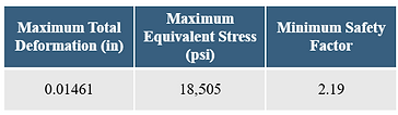
From these results I was able to conclude that the design experienced a low stress, little deformation, and a satisfactory factor of safety. A table showing the results is below:
Trade Study:
This analysis was run on all three designs and a trade study was performed to aid in the selection of shelves to move onto prototyping. In this trades study the shelves weight, interoperability, manufacturing, factor of safety, and deformation were all considered.
Prototyping:
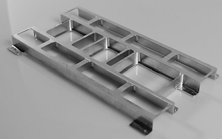
From the trade study Designs A and B were selected for prototyping. These two shelves in addition to the current design all were manufactured out of aluminum 6061. These shelves were CNC'd at 50% scale due to cost and limitations of the CNC mill. Below are pictures of the current design as well as design A.

Design A Prototype
Testing:
A three-point bend test was preformed on all of the prototypes to see how they preformed against each other. The objective of this test was to determine the deflection of the test specimen under the design and ultimate load. This test was preformed in a UTS machine where a custom test stand needed to be developed in order to support the shelves. When designing the test stand I considered testing standards to ensure that the test stand allowed for a 10% overhang on each end and that the stand had the proper span to thickness ratio. This stand was manufactured from steel and was designed with a factor of safety greater than 5 to ensure that the test specimen would deform before the test stand would.
Testing Results:
From the testing we were able to determine that both of the shelves minimally deformed under the ultimate load. From the testing we generated a load vs. deflection graph to visualize how each shelf responded to the load.
All three of the designs are in the linear region which means that under the ultimate load the shelves are within the elastic region and do not permanently deform under these loads. We also determined that due to the weight reduction on the shelves the deflection increased marginally but, still within the project constraints.
After testing was completed designs A and B were compared against each other based off the criteria mentioned in the trade study. From this comparison it was ultimately determined that due to design A having greater weight savings, better manufacturability/integration, and a lower deformation it would be the final design for avionics shelf.
This shelf is a 47% reduction in weight from the current shelf. Which when implemented into the chinook will save around 13 pounds. This weight savings carries significant operational, financial, and strategic importance for Boeing. The baseline avionics rack contributes to unnecessary aircraft weight, which directly impacts fuel consumption, payload capacity, and long-term operating costs. By implementing this lighter weight rack Boeing can improve overall efficiency and reduce lifecycle costs in the CH-47 Chinook.

3D Model of Current Ch-47 Chinook Avionics Rack

3D Model of Current Ch-47 Chinook Avionics Shelf

Current Shelf Total Deformation (in)

Animation of the First Harmonic

Proposed Design C
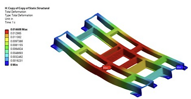
Design A Total Deformation (in)

Design A Equivalent Stress (psi)


Design A Prototype: Horizontal Stringers
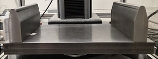
Test Stand
Proposed Design A Features:
I personally worked on the design of proposed design A. From the FEA I identified multiple locations where I could remove material without affecting the performance of the structure overall. This led to multiple sections of the current shelf to be removed. With this I then ran more FEA on my design to see if it met the criteria specified by Boeing. This analysis allowed me to identify key area where I would need to add some reinforcing to ensure that the piece had a high factor of safety and minimal deflection all while reducing the weight. This led to the addition of thick stringers, which were placed along the central axis of the avionics that reside on the shelf.
Some key features of this design are as follows:
-
Cooling holes for fan tubing
-
Attaches using current mounting hardware
-
Allows for easy installment
-
-
Shelf is designed to be tailored specifically to the avionics on the shelf
-
Lightweight
-
47% reduction in weight from the current design
-
Current Design Prototype

Citrus Racing (FSAE) | Aerodynamics Project & Composites Lead
Aerodynamics Project Lead:
As an Aerodynamics project lead I was responsible for the design and analysis of the front wing design for Citrus Racing. As a project lead I had to design the front wing of the car within a tight timeline of a couple weeks, taking into account, performance, weight, structure, and manufacturability of the wing.
Design Criteria:
-
The wing should generate a downforce greater than its own weight
-
The wing shouldn't break under downforce loads or in the event of a crash
-
The wing should be able to be manufactured in house
Given these criteria I started to look at what other current formula SAE teams do for their front wings to get some ideas regarding wing shape and airfoil locations. With this information I specked two airfoils that would be used for the wing.
For the first airfoil the one on the bottom of the wing I went with a design that has a high coefficient of lift and a low coefficient of drag at a lower angle of attack. This is because this wing will be very close to an angle of attack of zero. This would allow for the lower wing to generate the max amount of downforce in this position.
For the second airfoil which would sit at a high angle of attack just above the first airfoil I decided to go with a airfoil that had a high lift to drag ratio at that high angle of attack. When deciding on the angle of attack I tried to pick a range in which the flow coming off the wing would go over the tires and suspension to help reduce the overall drag of the car.
Wing Analysis:
After the wing was fully designed I ran CFD on the wing using ANSYS Fluent. I ran this simulation over the full wing assuming that the car was driving at a speed of 30 mph.
From the simulation I was able to get that at this speed the front wing will produce around 45 lbs of downforce while only generating around 7.5 lbs of drag.
Wing Manufacturing:
In order to manufacture the wing in house, the wing had to be made out of readily available materials that the team had experience in. To make the wings I 3D printed them from PETG in order to ensure that the wings were light while also being strong enough to withstand the applied loads. For the other components such as the winglets and the connecting rods I manufactured them from carbon fiber to again allow for the wing to as light as possible while still being able to perform.


Nosecone:
The nosecone was the largest piece that I manufactured. This was also the largest piece that the team has manufactured in three years. With this piece I was the in charge of a team of three engineering students. My team and I worked to manufacture the plug for the nosecone in which we used to lay the carbon onto. We manufactured the plug from high density foam as it allowed us to use the CNC mill to cut the layers out. This allowed for the plug to be as accurate as possible to the CAD design.

Nosecone Mold
Once the plug was complete my team and I cut the carbon sheets out to wrap around the nosecone. We used six layers on the nosecone and used a similar method with the two different weaves as I did for the floor. Once the carbon was done curing the plug was removed from the nosecone and we had a fully finished nosecone which will be implemented onto the car.

After the mold was printed I layered the carbon pieces onto the mold and created a vacuum bag around the layers. I used this bad to pull the epoxy through the piece using a vacuum chamber. This method allowed for the piece to hold the molds shape well all while producing a smooth finish.


Nosecone Layup
Fully Finished Nosecone

Composite Lead:
As the composite lead for Citrus Racing I was responsible for the manufacturing of the aerodynamic components of the car. As the composite lead I am responsible for overseeing all of the carbon fiber manufacturing.
Responsibilities include the design/manufacturing of the molds, specking of the carbon sheets, development of manufacturing processes for the aerodynamic components, and the laying up of the components.
The Floor:
One of the first pieces I manufactured was the floor for the car. For this piece I went with two different weaves of carbon and a total of five layers. I decided to do with this layup as the floor will often see different types of debris which could potentially damage the piece or injure the drive. As for the weaves I decided to go with a tight 12k twill weave and a thicker unidirectional weave. The 12k twill weave was used for the first four layers to ensure that the piece could withstand all forces applied. The thicker UD weave was applied last as this weave would help with the dispersion of the load if a larger rock were to hit the floor.
For the mold I 3D printed the shape of the floor section that I would use to lay carbon on top of.This would allow me to capture the curve of the floor all while producing a cheap mold.

CAD Model of the Front Wing
Vacuum Bagging of the Floor
Fully Manufactured Floor
Velocity Path-lines of the Front Wing
Fully Manufactured Front Wing

Avionics:
-
Current Electronic Components
-
Teensy LC 4.1 - Microcontroller
-
MPU9250 – Accelerometer
-
BMP280 – Barometer
-
TBS Crossfire Nano RX - Transceiver
-
Voltage Regulator and Power Supply
-
2 Tower Pro MG90SMicro Servos
-
BlueJay Altimeter
-
4 Black powder e-matches

Aerospace Capstone | Sounding Rocket Design
Small Scale Vehicle I (SSV I):
In order to validate our initial design for the rocket my team and I decided that we should to small low risk launches. These launches would be of 30% scale vehicles to ensure that our vehicle was statically stable and that all systems were functioning properly before scaling the rocket up.
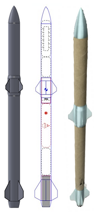
CAD Model, OpenRocket, and final prototype of SSV I
This design features two sets of fins. The rear fins are designed to help with static stability and the forward canards were put in place to simulate the fin placement for a fin controlled rocket design. This rocket was designed with a static controls section as we wanted to test the rockets stability before implementing a controls systems. The vehicle specs can be seen below:
Avionics and Control System:
-
Static control section
-
Teensy LC 4.1
-
BMP 280 Barometer
-
MPU 9250 9 DOF Accelerometer
Recovery System:
-
Two stage system using motor back charge
-
24" Nylon parachute
-
Cellulose wadding to protect chute
-
Uses timed delay charge to eject at apogee
Vehicle Specs:
-
Mass: 1.27 kg
-
Height: 2.60 ft
The Launch:
What Went Well
-
Successful launch and ascent phase:
-
Avionics fully operational upon launch
-
Stages remained coupled until desired stage separation
-
-
Back-charge was effective in separating stages and ejecting parachute and insulation
-
Red zone calculations accurately predicted impact site
-
Fully-functioning avionics recovered after impact
-
Stages withheld forces of flight
-
Structural damage solely resulted from impact
-

OpenRocket and final prototype of SSV II
Avionics and Control System:
-
Active control section
-
Teensy LC 4.1
-
BMP 280 Barometer
-
MPU 9250 9 DOF Accelerometer
Recovery System:
-
Single stage system using motor back charge
-
24" Nylon parachute
-
Nylon webbing strap connecting stages to chute
-
Cellulose wadding, flame blankets to protect chute
-
Uses timed delay charge of 7 seconds to eject at apogee
Payload:
-
Payload mass of 18oz
-
Used to simulate location of future payload and to help with CG location
The Launch:
What Went Well
-
The parachute was successfully deployed
-
The control system successfully activated during flight
-
Flight data was recorded and recovered
Full Scale Vehicle:
Recovery System:
-
We plan to use a common drogue/main parachute recovery system utilizing a dual back-charge deployment
-
Small quantity of black powder with an ignitor controlled by the primary flight computer [BlueJay]
-
The black powder charges will break shear pins which hold the sections in place
-
24-inch diameter spherical drogue parachute for controlled fast descent from apogee
-
96-inch doughnut geometry main parachute for final deceleration when vehicle reaches less than 1000 feet AGL
Payload:
-
Payload mass of 700g
-
Used to simulate location of future payload and to help with CG location
Propulsion System:
-
Aerotech G80-7T
-
Thrust: 17 lbf
-
Impulse: 31 lbf-sec
Lessons Learned
-
Individually tethering each stage to parachute prevents a failure in one stage from affecting the other
-
Saving a backup of data on avionics internal memory and/or wirelessly transmitting data to ground computer prevents physical data loss
-
Fine tolerance of 3D-printed parts is inconsistent when designing press, sliding fits
-
Remote motor detonation allows greater distance between launch crew and test stand
Lessons Learned
-
Cp location and static margin will vary at low speeds and can cause launch kickbacks
-
Fins need to be fully secured to the vehicle
-
Avionics need to be fully secured to the rocket

Video of Control System
Vehicle Specs:
-
Mass: 3 lbs
-
Height: 2.60 ft
-
Diameter: 1.642”
-
CG: 15.787”
-
CP: 21.868”
-
SM: 6.081”
Propulsion System:
-
Aerotech G80-7T
-
Thrust: 17 lbf
-
Impulse 31: lbf-sec
Lessons Learned
-
Cp location and static margin will vary at low speeds and can cause launch kickbacks
-
Fins need to be fully secured to the vehicle
-
Avionics need to be fully secured to the rocket
Vehicle Specs:
-
Mass: 260 oz
-
Height: 60”
-
Diameter: 2.56”
-
CG: 32.74”
-
CP: 44.025”
-
SM: 11.285”
Propulsion System:


OpenRocket and CAD of Final Vehicle
Project Overview:
Design, launch, and testing of a rocket carrying a payload weighing 4.45 lbs to a target apogee of 10,000 ft Above Ground Level (AGL). The rocket must have onboard avionics to log flight data and control stage separation. The rocket will also feature an active attitude control system which will help stabilize the rocket during its assent phase.
Team Role:
I was responsible for the deign and implementation of the vehicles. I worked in OpenRocket and SolidWorks to generate the designs of the rocket. In addition I was responsible for the integration of all the sub-systems. I had to ensure that the payload, avionics, recovery, and propulsion systems could all fit within the rocket and that they would all successfully integrate with each other. I had to account for the space of each system, the placement of the systems, how they interact with each other, and how they all affect the center of gravity and center of pressure to ensure the rocket remains statically stable.
Project Plan:
-
Rocket Design
-
Small Scale Vehicle Development
-
Small Scale Testing
-
Small Scale Launches
-
Full Scale Vehicle Development
-
Full Scale Testing
-
Full Scale Launch
What Went Wrong
-
Static instability at low velocity caused a 60° pivot down-range shortly after launch
-
On touchdown one of the fins with the control surface broke off
-
Prior to launch telemetry had hardware issues which caused it to not be active during launch
What Went Wrong
-
Parachute-Stage tether burnt in back-charge ignition
-
Parachute ejected from airframe lost in wind
-
Stages left to fall separately of each other
-
-
SD card used for data recording lost on ground impact
-
Impact irreparably damaged phenolic airframe and 3D-printedcomponents
-
Loosely-fitting stage coupler contributed to vibration and bucking through early ascent
Small Scale Vehicle II (SSV II):
After the launch of the SSV I my team and I moved on to the development of the SSV II. This vehicle featured improvements made on the design and implementation of all the systems. For this rocket we implemented changes within the recovery and avionics systems to ensure that our failures from the last rocket wouldn't happen again. We also implemented and active attitude control section on this rocket. Based off the first launch my team and I decided that the forward canards would pose to much of an issue with controlling the rocket due to the level of control authority they have. For this design we switched to implementing little control surfaces in the aft fins for the sole purpose of controlling the roll mode of the rocket.
Invent@SU | Wheelchair Docking System
Project Summary:
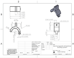
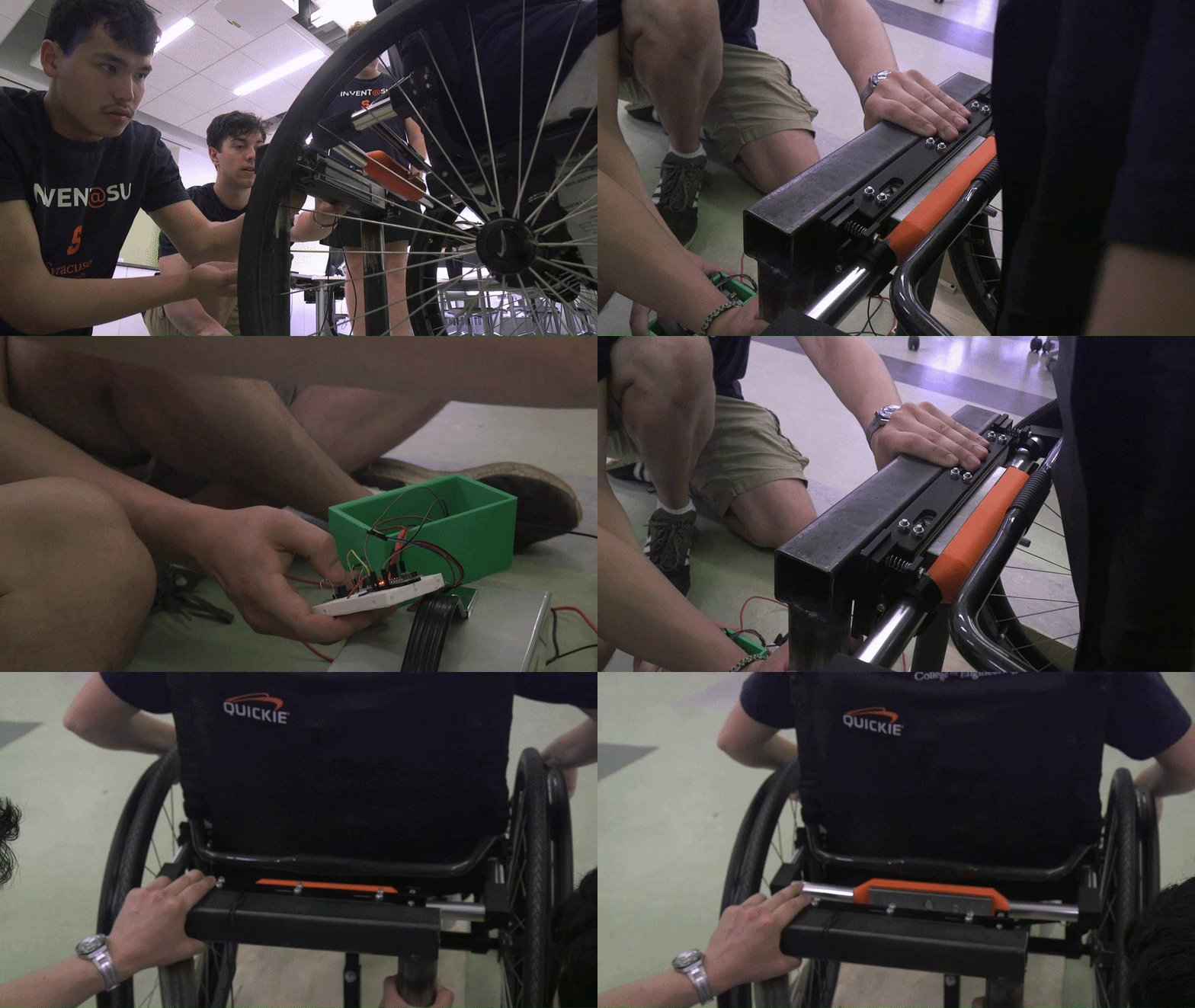
I took part in the Invent@SU design competition at Syracuse University where I had the opportunity to work with a multidisciplinary team to develop an electromagnetic wheelchair docking system that allows users to independently secure themselves in a vehicle as the existing solution required external assistance.
I applied my education, design, and prototyping skills to real world applications through the development of an electromagnetic wheelchair docking system for vehicles. I created multiple CAD drawings and assemblies using Solidworks as well as completing a full stress analysis on the product to ensure that it could withstand the forces of a car crash. I gained valuable skills in communication while pitching our invention to a panel of judges that consisted of investors and alumni.
Project Approach:
-
Designed 3D models and assemblies in SolidWorks
-
Preformed structural analysis to ensure crash safety compliance
-
Test multiple designs under time and budget constraints
Project Result:
We developed a product within a short timeline for our client, a former Syracuse University student and quadriplegic that allowed him to attach himself to his vehicle giving him freedom and independence overall taking second place in the competition. We are currently working towards pursuing a provisional patent.